Introduction
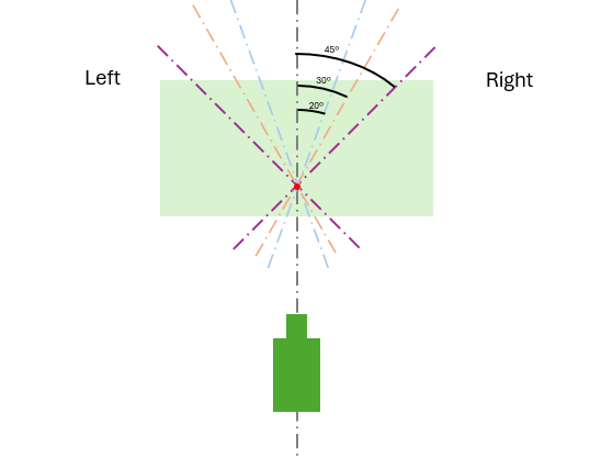
This experiment investigates how varying the surface reflection angle affects laser vibrometer measurements. A vibrometer is aligned at several angles relative to the motion of a shaker’s stinger — orthogonally (0º), and at ±20º, ±30º, and ±45º. The results are compared to assess the accuracy of angle-corrected reconstructions.
Protocol
-
Baseline Measurement: The vibrometer is initially aligned orthogonally (0º) to the shaker stinger. This measurement serves as the ground truth reference.
-
Angled Measurements: The measurement surface is tilted to ±20º, ±30º, and ±45º, and the corresponding velocity responses are recorded for each angle.
-
Correction and Averaging: Opposing angle pairs are averaged and corrected using cosine projection to estimate the longitudinal component.
Mathematical Background
1. Projection Correction
The vibrometer measures the velocity projected onto its axis. For a laser angled at θ, the measured velocity is:
\[V_{\text{meas}} = V_z \cdot \cos(\theta)\]To recover the true longitudinal velocity:
\[V_z = \frac{V_{\text{meas}}}{\cos(\theta)}\]2. Averaging Symmetrical Angles
Opposing measurements (e.g., +θ and -θ) are averaged and corrected:
\[V_z^{(\theta)} = \frac{V_{+\theta} + V_{-\theta}}{2 \cos(\theta)}\]The full estimate uses all three angle pairs:
\[V_z^{\text{avg}} = \frac{1}{3} \left( V_z^{(20^\circ)} + V_z^{(30^\circ)} + V_z^{(45^\circ)} \right)\]3. Relative Error in Decibels
To quantify the difference between an estimated velocity and the orthogonal reference, we use:
\[\mathrm{Error}_{\mathrm{dB}}(f) = 20 \log_{10} \left| \frac{ \hat{V}(f) }{ V_{\text{ref}}(f) } \right|\]Where:
- 0 dB means perfect match
- Positive values indicate overestimation
- Negative values indicate underestimation
Results
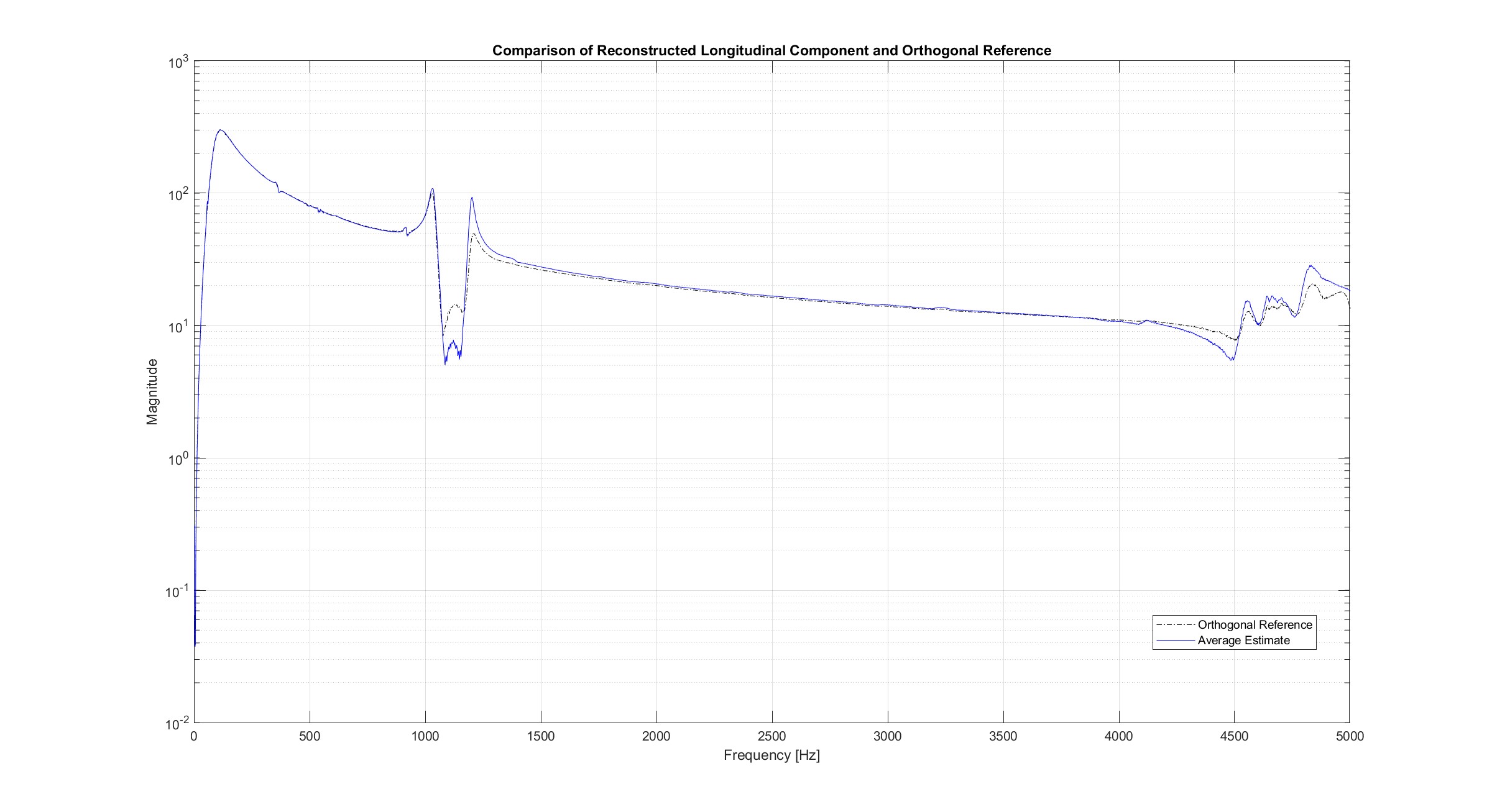
Orthogonal vs. Reconstructed Velocity
Comparison of the orthogonal velocity measurement and the averaged reconstruction from all corrected angle pairs:
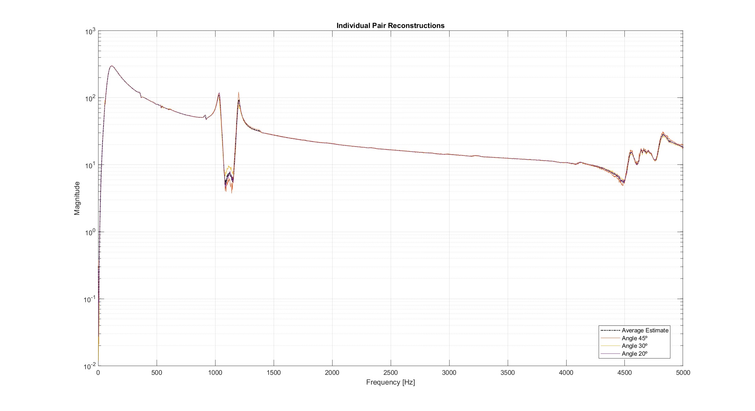
Individual Angle Contributions
This plot shows the corrected measurements from each angle pair individually:
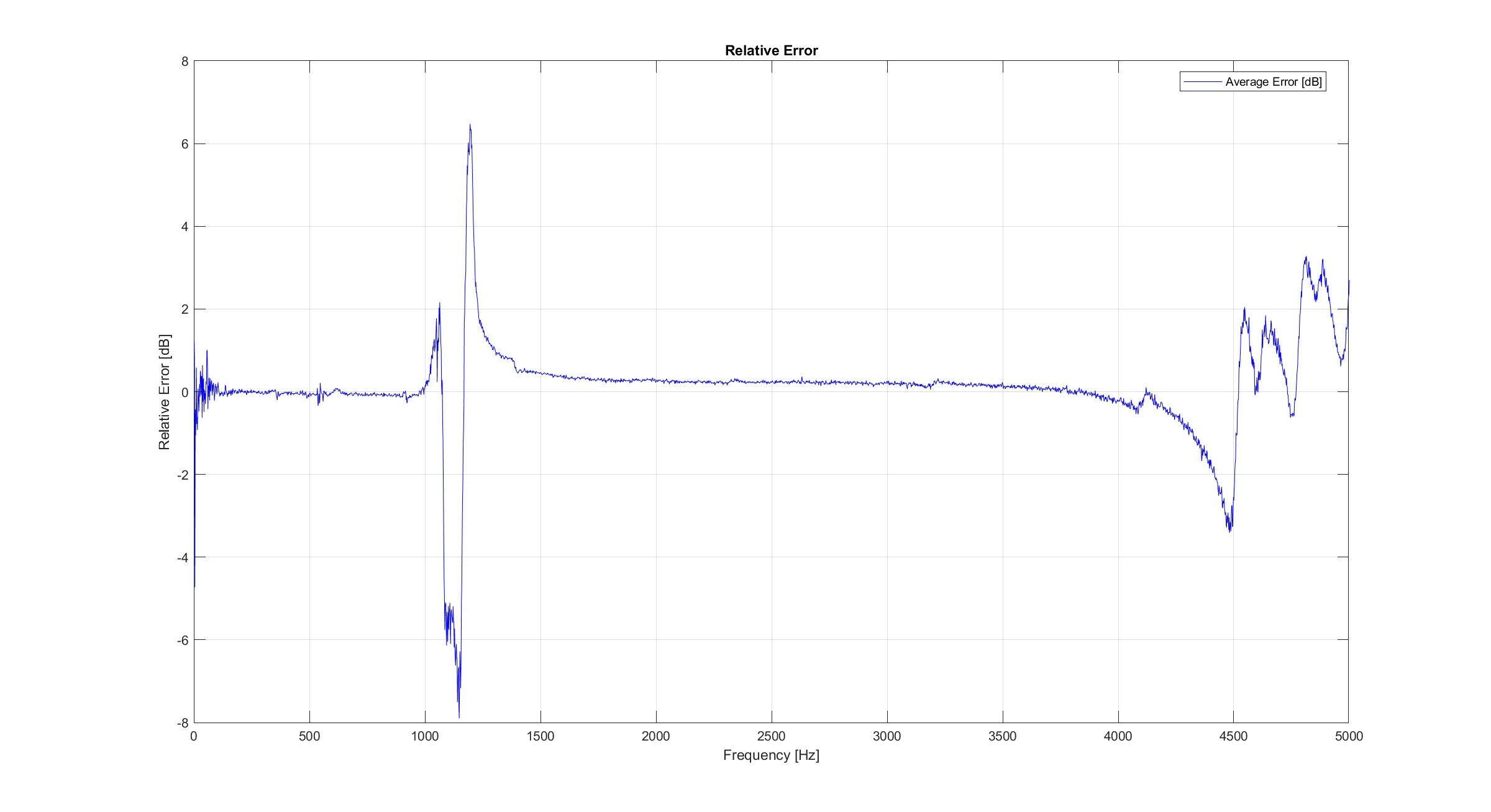
Relative Error with Respect to Orthogonal Measurement
The relative error (in decibels) quantifies how much each estimate deviates from the orthogonal reference:
Conclusions
Here are the two main conclusions:
- Non-orthogonal angles can be corrected using cosine projection.
- Averaging across angle pairs improves the results, since it cancels the in-plane vibrations (x and y).
Code and Data
The full source code and experimental data used are available on GitHub PhD repository.